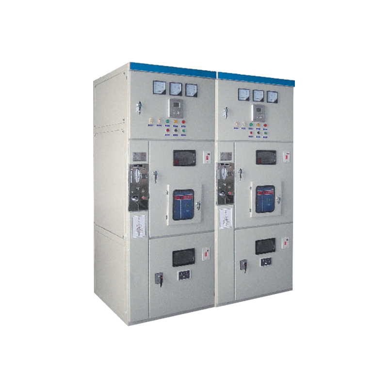
XGN66-12 Switch Cabinet Intelligent Control Power Distribution System GCS/GCK/MNS
XGN66-12 fixed closed switchgear (hereinafter referred to as switchgear) is our company’s new generation of high-voltage electrical complete sets of products, in line with national standards.The requirements of GB3906 “-35KV AC Metal-enclosed Switchgear” DLT404 “Technical Conditions for Ordering Indoor AC High Voltage Switchgear” of the Ministry of Electric Power are also full.Meet the international standard IEC60298 “Requirements for AC metal-enclosed switchgear and control equipment above 1KV and below 52KV.
This product has absorbed foreign advanced technology, it is small in size, which is only 50% of the protection of ordinary switch cabinet; the circuit breaker has high reliability and good performance,”Five The “anti-” interlocking mechanism is reliable and simple. The switch cabinet is an indoor complete set of 3.6, 7.2, 12KV three-phase alternating current 50HZ single busbar segmentation, as To receive and distribute electrical energy. It also has the functions of controlling, protecting and monitoring circuits, and can be used in various types of power plants, substations, and industrial and mining enterprises.High-rise buildings and other places can also be combined with the ring network to be used in opening and closing stations.
Model meaning
● Install a vacuum circuit breaker ● Rated voltage (KV) ● Design Number ● indoor ● Withdrawable ● Armoured
Normal use environmental conditions
1. Ambient temperature: -25°C~+40°C, the average temperature within 24 hours does not exceed +35°C. 2. The altitude does not exceed 1000m. 3. The horizontal inclination is not more than 3°C. 4. The seismic intensity does not exceed 8°C 5. There is no violent vibration, shock and explosion hazard place.
Structural features
1. The cabinet body is welded with high-quality angle steel. 2. The circuit breaker room is located in the middle (lower) part of the cabinet, which is convenient for installation, debugging and maintenance. It is equipped with ZN63A (VS1-12) circuit breaker as standard, and has a pressure release channel to ensure personal safety. 3. Using advanced and reliable rotary isolating switch, it can safely enter the circuit breaker room for maintenance when the main bus is live. 4. The protection level of the whole cabinet is IP4X. 5. Equipped with a reliable and fully functional compulsory mechanical locking device, which can easily and effectively meet the requirements of “five preventions”. 6. Have a reliable grounding system. 7. The door is equipped with an observation window, which can clearly observe the working status of the components in the cabinet. 8. The operating mechanism is locked using the same JSXGN locking mechanism used in the XGN12-12 cabinet, which is simple, reliable, convenient and practical. 9. The incoming and outgoing cables are lower than the front of the cabinet bottom, which is convenient for users to connect.
The main technical parameters
Serial number
project
unit
technical parameter
1
Rated voltage
KV
3.6,7.2,12
1
Rated power frequency withstand voltage
KV
To the ground, alternately: 42: Fracture: 48
3
Rated lightning impulse withstand voltage
KV
To the ground, alternately: 75: Fracture: 85
4
Rated frequency
HZ
50
5
Rated current
A
630,1250
6
Rated short-circuit breaking current (effective value)
KA
20,25,31.5
7
Rated short-circuit making current (peak value)
KA
50,63,80
8
Rated dynamic steady flow (peak value)
KA
50,63,80
9
Rated thermal stability current 4S(effective value
KA
20,25,31.5
10
Protection level
IP4X
11
Dimensions (width x depth x height)
mm
900*1000*2300
12
weight
Kg
≈600
Serial number
project
unit
technical parameter
1
Rated voltage
KV
12
1
Rated current
A
630 1250
3
Rated short-circuit breaking current
KA
20,25,31.5
4
Rated short-circuit making current
KA
50,63,80
5
Rated short-time withstand current (4s effective value)
KA
20,25,31.5
6
Rated peak withstand current (peak)
KA
50,63,80
7
Mechanical life
order
10000
8
Rated short-circuit breaking current breaking times
order
50
9
Rated operating sequence
0.3s-180s
10
Contact opening distance
mm
11±1
11
Contact stroke
mm
4±0.5
12
Center distance between phases
mm
210
13
Opening speed
m/s
41.2±0.2
14
Closing speed
m/s
0.6±0.2
15
Opening time
ms
≤60
16
Closing time
ms
≤75
17
Three-phase opening synchronization
ms
≤2
18
Closing bounce
ms
≤2
19
Loop resistance
μQ
≤45
20
Contact accumulative allowable wear thickness
mm
3
The technical parameters of other electrical components can be found in their respective operating instructions. If the rated current of the switchgear is greater than 1600A, the solution must be negotiated with our company.
1. Cabinet door
2. Lighting
3. Observation window
4. Operating mechanism
5. Small door panel
6.Instrument door
7. Brow
8. Busbar through wall bushing
9. Bolt
10. Washer
11. Washer
12. The mother
13. Isolating switch
14.Tie rod
15. Rear sealing plate
16. Current transformer
17. Vacuum circuit breaker
18. Isolating switch
19. Sensor
20. Bolt
21. Washer
22. Washer
23.Skeleton
24. Lightning arrester
Install
1. Refer to the figure below for the installation foundation. The foundation channel steel protrudes 1-3mm from the ground, and the unevenness per meter should not exceed 1.5mm, and the total length should not exceed 5mm. 2. Place the switch cabinet on the foundation in order and adjust the installation position. Then fix it with M12 bolts or spot welding, and tighten the cabinet with M8 bolts. 3. After disassembling the cover, install the main bus bar and the primary cable, and the contact surface of the terminal should be cleaned and coated with neutral petroleum jelly. After installation, please plug the cable hole once. 4. Connect the indirect ground bus of the cabinet to make it one body along the arrangement direction of the switch cabinet. Check whether there is any omission of the working and protective grounding, whether the grounding loop is continuously connected, and the working grounding resistance should be Not more than 1000μ Q, the protection connection resistance should not be less than 42. 5. Install the secondary cable from the bottom of the front of the cabinet, enter the low-voltage room along the side wall, and tap it on the terminal block; or lead into the low-voltage room from the secondary small bus on the top of the cabinet, and block the cable hole after installation. 6. Clean up the dust and debris in the cabinet.
Put into operation
1. The following inspections and adjustments should be carried out before putting into operation: A. According to the ordering requirements, check whether the models and specifications of the electrical components installed in the cabinet are consistent; check whether the fasteners are loose; check whether the first and second wiring are correct; operate the isolation switch,The grounding switch, circuit breaker, and mechanical interlocking should be flexibly free from jamming for 3 to 5 times, and the interlocking should meet the requirements of “five preventions”, and then lubricate the moving parts of the machine. B. Check the insulation level and loop resistance of the switchgear and the mechanical characteristics of the circuit breaker according to Article 3 of this manual and the factory test report. The test results should be consistent or similar to the factory test report.
Random documents and attachments
1. Product qualification certificate and packing list; 2. Installation instructions and secondary wiring diagrams of switch cabinets and main non-components; 3. Energy storage and operating handle; 4. For other spare parts users, please consult with our company.
Order notice
1. A wiring plan diagram and a wiring plan arrangement diagram; 2. Secondary circuit schematic diagram, wiring diagram, terminal arrangement diagram; 3. List of primary and secondary equipment; 4. The layout of the switch cabinet and the installation position of the busbar tray; 5. Please consult with our company for special conditions of use of spare parts and equipment.
Our products boast customizable materials and dimensions, ensuring a tailored experience. With a range of materials to choose from and the ability to adjust sizes to your liking, our offerings are designed to meet your unique needs and preferences.
Saipwell is a subsidiary of Saip Electric Group and is a leader in the global enclosure market. Its main business involves the manufacturing of electrical and IT enclosures, assembly of whole electrical switchgear systems and development of enclosures for use in new energy solutions
This website uses cookies so that we can provide you with the best user experience possible. Cookie information is stored in your browser and performs functions such as recognising you when you return to our website and helping our team to understand which sections of the website you find most interesting and useful.
Strictly Necessary Cookies
These cookies are essential to provide you with services available through our website and to enable you to use certain features of our website.
Without these cookies, we cannot provide you certain services on our website.
If you disable this cookie, we will not be able to save your preferences. This means that every time you visit this website you will need to enable or disable cookies again.
Tracking cookies
These cookies are used to collect information to analyze the traffic to our website and how visitors are using our website.
For example, these cookies may track things such as how long you spend on the website or the pages you visit which helps us to understand how we can improve our website for you.
The information collected through these tracking and performance cookies do not identify any individual visitor.
Please enable Strictly Necessary Cookies first so that we can save your preferences!
Targeting and advertising cookies
These cookies are used to show advertising that is likely to be of interest to you based on your browsing habits.
These cookies, as served by our content and/or advertising providers, may combine information they collected from our website with other information they have independently collected relating to your web browser's activities across their network of websites.
If you choose to remove or disable these targeting or advertising cookies, you will still see adverts but they may not be relevant to you.
Please enable Strictly Necessary Cookies first so that we can save your preferences!
Cookie Policy
Your privacy is important to us
Cookies are very small text files that are stored on your computer when you visit a website. We use cookies for a variety of purposes and to enhance your online experience on our website (for example, to remember your account login details).
You can change your preferences and decline certain types of cookies to be stored on your computer while browsing our website. You can also remove any cookies already stored on your computer, but keep in mind that deleting cookies may prevent you from using parts of our website.