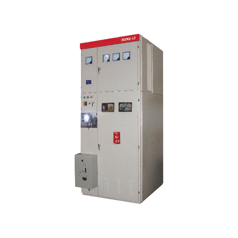
XGN2-12 Low Voltage Metal Indoor AC switchgear Withdrawable
Product description XGN2- 12 box-type fixed AC metal-enclosed switchgear (switch cabinet for short) is based on the national standard GB3906 “3-35kV AC metal-enclosed Switchgear” standard, meets the domestic IEC298 standard, and meets the “five prevention” locking requirements proposed by the two parts. Scope of application This product is suitable for three-phase AC single bus, double […]
XGN2- 12 box-type fixed AC metal-enclosed switchgear (switch cabinet for short) is based on the national standard GB3906 “3-35kV AC metal-enclosed Switchgear” standard, meets the domestic IEC298 standard, and meets the “five prevention” locking requirements proposed by the two parts.
Scope of application
This product is suitable for three-phase AC single bus, double bus, single bus with bypass system with rated voltage of 3.6-12kV, 50Hz and rated current of 630-3150A for receiving and distributing electric energy. It can meet the requirements of various types of power plants, substations (substations) and industrial and mining enterprises.
Model Meaning
Normal use environmental conditions
1. Ambient temperature: The upper limit is +40°C, the lower limit is -10°C, and the daily average value of saturated vapor pressure allowed to be stored and transported at -30°C is not more than 2.2x 10⁻³mpa, and the monthly average value is not more than 1.8x 10- 3mpa; 2. Relative humidity: the daily average value is not more than 95%, and the monthly average value is not more than 90%; 3. Altitude: below 1000m (when it exceeds 1000m, it can be produced in consultation with the manufacturer); 4. Seismic intensity: less than 8 degrees; 5. There is no place with fire, explosion hazard, serious pollution, chemical corrosion and severe vibration.
Normal use environmental conditions
(1) Main technical parameters of switchgear
Serial number
project
unit
technical parameter
1
Rated voltage (maximum working voltage)
KV
3.6,7.2,12
1
Rated current
A
630-3150
3
Rated short-circuit breaking current
KA
16,20,31.5,40
4
Rated short-circuit making currenf (peak value)
KA
40,50,80,100
5
Rated short-circuit dynamic stabity current (peak value)
KA
40,50,80,100
6
Rated thermal stability current
KA
16,20,31.5,40
7
Rated thermal stability time
S
4
8
Protection level
IP3X
9
Busbar system
Single busbar segmentation
10
Operation method
Electromagnetic type, spring energy storage type
11
Dimensions (width x depthi x height)
mm
1100*1200*2650(The general type)
12
weight
Kg
1000
(2) Technical parameters of main electrical equipment in the switch cabinet
a. Technical parameters of ZN28A-12 vacuum circuit breaker
Serial number
project
unit
technical parameter
1
Rated voltage (maximum working voltage)
KV
3.6,7.2,12
1
Rated current
A
630-3150
3
Rated short-circuit breaking current
KA
16,20,31.5,40
4
Rated short-circuit making currenf (peak value)
KA
40,50,80,100
5
Rated short-circuit dynamic stabity current (peak value)
KA
40,50,80,100
6
Rated thermal stability current
KA
16,20,31.5,40
7
Rated thermal stability time
S
4
8
Protection level
IP3X
9
Busbar system
Single busbar segmentation
10
Operation method
Electromagnetic type, spring energy storage type
11
Dimensions (width x depthi x height)
mm
1100*1200*2650(The general type)
12
weight
Kg
1000
Structural characteristics
The XGN2-12 switchgear is a metal enclosed box structure. The frame of the cabinet was originally designed by welding angle steel. Later, it can also be a steel plate bending assembly structure developed by our company, which greatly increases the appearance and is easy to organize. Production, shorten the production cycle. The cabinet is divided into a circuit breaker room, a busbar room, a cable room, a relay room, etc., and the rooms are separated by steel plates. (1). The circuit breaker room is in the lower part of the front of the cabinet. The rotation of the circuit breaker is connected with the operating mechanism by the pull rod. The upper wiring terminal of the circuit breaker is connected with the upper isolating switch, and the lower wiring terminal of the circuit breaker is connected with the current transformer, and the current mutual inductance The breaker is connected to the busbar of the lower isolating switch, and the circuit breaker room is also equipped with a pressure release channel. If an internal arc occurs, the gas can release the pressure through the exhaust channel. (2). The busbar compartment is in the upper part of the back of the cabinet. In order to reduce the height of the cabinet, the busbars are arranged in a product shape, supported by 7350N bending strength porcelain insulators. The busbars are connected to the upper isolating switch busbar, and the adjacent two busbar chambers Can be isolated between. (3). The cable room is at the rear of the lower part of the cabinet. The supporting insulator in the cable room can be equipped with a voltage monitoring device, and the cable is fixed on the bracket. When the main wiring is a contact plan, this room is a contact room. The relay room is in the front of the upper part of the cabinet. The indoor installation board can be installed with various relays. There are terminal block brackets in the room. The door can be installed with secondary components such as indicating instruments and signal components. The top can also be equipped with a secondary small bus. (4). The operating mechanism of the circuit breaker is installed at the lower left position, and the upper part is the operating and interlocking mechanism of the isolating switch. The switch cabinet is double-sided maintenance. The secondary components of the relay room are inspected in front, the operating mechanism is maintained, the mechanical interlocking and transmission parts, and the circuit breaker is inspected. The main bus and cable terminals are repaired at the back, and there are lights in the circuit breaker room and the cable room. Below the front door is a grounded copper bus bar parallel to the width of the cabinet, with a cross section of 4 x 40mm2. (5).Mechanical interlock: In order to prevent the disconnecting switch with load, prevent the circuit breaker from being switched on and off by mistake, and to prevent the electric interval from being mistakenly entered; prevent the grounding switch from being switched on when the power is on; prevent the switch with a grounding knife from being switched on, the switch cabinet adopts corresponding machinery Interlock, the principle of action of mechanical interlock is as follows: a. Power failure operation (operation-overhaul) The switch cabinet is in the working position, that is, the upper and lower isolation switches and circuit breakers are in the closed state, the front and rear doors have been locked, and are in live operation, and the small handle is in the working position. First open the circuit breaker, and then pull the small handle to the “breaking lock” position. At this time, the circuit breaker cannot be closed. Insert the operating handle into the operating hole of the lower isolation and pull it down from the top to the bottom to isolate and open the circuit breaker. Position, remove the handle and insert it into the upper isolation operating hole, pull it down from the top to the upper isolation opening position. Then take down the operating handle, insert it into the operating hole of the grounding switch, and push it from bottom to top to make the grounding switch in the closed position. At this time, pull the small handle to the “overhaul” position. You can open the front door first, take out the key behind the door and open the back door. After the power failure operation is completed, the maintenance personnel will maintain and repair the circuit breaker room and the cable room. b. Power transmission operation (overhaul-run) If it has been overhauled, it needs to be powered on. The operating procedure is as follows: Close the rear door, take out the key and close the front door, and move the small handle from the “inspection” position to the “disconnecting lock” position. At this time, the front door is locked and the circuit breaker cannot be closed. Insert the operating handle into the grounding switch operating hole, Pull down to make the grounding switch in the open position, remove the operating handle, and then insert it into the operating hole of the upper isolation, push it from the bottom up to make the upper isolation in the closing position, remove the operating handle, and insert the operation of the lower isolation In the hole, push from the bottom to the top to make the bottom isolation in the closing position, take out the operating handle, and pull the small handle to the working position. At this time, the circuit breaker can be closed
Our products boast customizable materials and dimensions, ensuring a tailored experience. With a range of materials to choose from and the ability to adjust sizes to your liking, our offerings are designed to meet your unique needs and preferences.
Saipwell is a subsidiary of Saip Electric Group and is a leader in the global enclosure market. Its main business involves the manufacturing of electrical and IT enclosures, assembly of whole electrical switchgear systems and development of enclosures for use in new energy solutions
This website uses cookies so that we can provide you with the best user experience possible. Cookie information is stored in your browser and performs functions such as recognising you when you return to our website and helping our team to understand which sections of the website you find most interesting and useful.
Strictly Necessary Cookies
These cookies are essential to provide you with services available through our website and to enable you to use certain features of our website.
Without these cookies, we cannot provide you certain services on our website.
If you disable this cookie, we will not be able to save your preferences. This means that every time you visit this website you will need to enable or disable cookies again.
Tracking cookies
These cookies are used to collect information to analyze the traffic to our website and how visitors are using our website.
For example, these cookies may track things such as how long you spend on the website or the pages you visit which helps us to understand how we can improve our website for you.
The information collected through these tracking and performance cookies do not identify any individual visitor.
Please enable Strictly Necessary Cookies first so that we can save your preferences!
Targeting and advertising cookies
These cookies are used to show advertising that is likely to be of interest to you based on your browsing habits.
These cookies, as served by our content and/or advertising providers, may combine information they collected from our website with other information they have independently collected relating to your web browser's activities across their network of websites.
If you choose to remove or disable these targeting or advertising cookies, you will still see adverts but they may not be relevant to you.
Please enable Strictly Necessary Cookies first so that we can save your preferences!
Cookie Policy
Your privacy is important to us
Cookies are very small text files that are stored on your computer when you visit a website. We use cookies for a variety of purposes and to enhance your online experience on our website (for example, to remember your account login details).
You can change your preferences and decline certain types of cookies to be stored on your computer while browsing our website. You can also remove any cookies already stored on your computer, but keep in mind that deleting cookies may prevent you from using parts of our website.